
Beginning CAD Design: Using Your Own Artwork to Create a 3D Model
- Nov 9, 2016
- 5 min read
Interested in learning how to design 3-dimensional objects but don't know where to start? We recommend TinkerCAD. This is a web-browser-based software that is free to use with sign-up that enables beginning CAD designers to get their feet wet in the design process. Using TinkerCAD is extremely easy and intuitive and is a great place to start your 3D design journey.
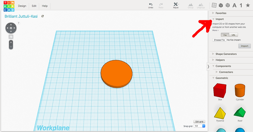
To begin designing, head over to tinkercad.com and sign up for an account. You will automatically be directed to their first tutorial and can follow along to learn the basics. I recommend going through the first few tutorials just to familiarize yourself with the layout and the functions that are available to you. You can always exit the lesson by selecting the "exit lesson" option at the top of the page. To get to the empty workplane showed below, choose the "start a new project" option.

For this demonstration, I will show you how you can create a custom keychain using the options provided in tinkerCAD or your own artwork.
On the left side of the page are your View options. You can zoom in and out with the "+" and "-" signs and pan around the 3D plane with the D-pad. On the right side of the page you will see a sort of tool bar that contains the functions you will use to create your object. To get your base design, select a shape after clicking on the "geometric" option (image of solid cube) and drag it into the workplane. I have chosen the cylinder.
You will notice that at the top right of your workplane there is a small box titled "Inspector." This allows you to determine whether your object is a solid (and its representative color) or if it is a hole. This will come in handy later, but for now we will keep the Inspector as it is.

I have chosen a cylinder as my first shape. The default size is 20mmx20mm but you can adjust the size of your shape along all axes by dragging the small white boxes into your desired positions as shown:


After you have chosen the dimensions of your base shape, it is time to either upload your own artwork or use the existing shape, symbol, number, or letter options that are available to you by default on tinkerCAD.

To use your own artwork, all you have to do is take a photo of or scan the art you want to become a part of your model and convert it into an SVG file using this online file converter. Please keep in mind that for the best results, you will want to use pictures that have high contrast and that are relatively simple. Using a black marker on a white paper produces great results as in the example of the flower to the right. You also have the option to use artwork that you have found on the internet by directly converting an image using its URL.
Sidenote: If you are familiar with Adobe Illustrator and work with more complex art sketches, it would be a good idea to convert your sketches into vector art format to reduce noise and then use this image to convert to the SVG file.
Once your SVG file is ready, go back to your tinkerCAD workplane and go to the "Import" section on the right toolbar. Choose your SVG file saved onto your computer (or the URL).
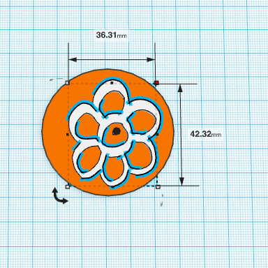
The larger the file is, the longer it will take to upload so I recommend sizing down your file by reducing the scale percentage - this is recommended for most scans or photos because these files are usually quite large. For my example, I have chosen a 15% scale and 10 mm height (both scale and height can be adjusted afterwards as well, so it is best to start small). After doing so, select "Import." Your image should appear in 3D on the workplane with your designated height as shown below in my project.

If you want to create a design using the shapes, symbols, numbers, or letters already available on tinkerCAD, you may directly select and drag the desired objects from the toolbar as I had already shown in the first step (when I chose the cylinder as my shape of choice) and continue with each following step.
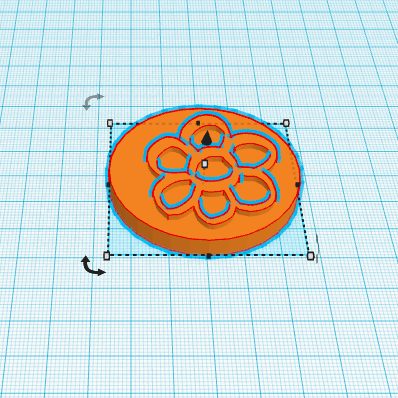
Then you can use the D-pad on the left to change your viewpoint so you can easily drag and resize your second object into the correct position and size. Below are the views of my object from above (left) and from the side (right). I decreased the size of the flower to fit within the cylinder and reduced the height to 8mm.

.

The "Inspector" setting for your second object will automatically be set on "color"meaning that your second object(flower) is a solid, having an additive effect to your first object (cylinder) but you may also change this to create a hole in the shape of your artwork (or shape/symbol/number/letter), having a subtractive effect. The hole will be gray in color as shown to the left.
If you wish to create a hole, you must make sure that the resulting object is all one piece. My example of the flower would not result in the desired object because when printed out, the center of the flower would not be connected to the rest of the printout.
For the purposes of this demonstration, we will go back to select the "color" option in the Inspector for an additive effect of the chosen artwork.
Once this is complete and you have your artwork in the desired position, you will want to select all of your objects by holding and dragging your mouse over the entire creation and then select the "Group" option on the top part of your toolbar. This merges the shapes that you have selected so that you can easily move the merged shapes as one object. You will notice that the merged object is now a single color (right).
Since we are making a keychain, we will need to add a hole to the current object for the keyring. This can be done by choosing a shape from the toolbar once again and dragging it over to your workplane, using the "Inspector" to choose the "hole" option. Then, just as we changed the scale and height of the artwork (flower), adjust the hole so that it fits into your object. I have chosen the hexagonal prism in the example as the shape for the hole.


Once this is complete, group your objects again so that the hole is now merged to be a part of the overall design. If you wish to add more objects or holes to your design, simply go back and follow each of these steps and remember to "Group" them at the end.

Now we have finished the design portion of this project and our file can be printed! Hover your mouse over the tab on the top left that is labelled "Design" and choose "Download for 3D Printing." If you are not finished with your project, you may also select "save" and it will be saved to your TinkerCAD account for use later.

Once you select "Download for 3D Printing," the following box will appear:

If you are using our ZEUS All-In-One 3D Printer, you will select the .STL format to save. You can either transfer the file wirelessly to ZEUS' onboard computer or use a USB stick to transfer the file. Then, you can proceed to slice your new .STL file with your desired settings and print out your design. If you are unfamiliar with any of these terms, please see our 3D Printing Terminology article. Below is the final printout!


If you have made any custom designs on your ZEUS, please share your photos with us by emailing them to sales@aiorobotics.com for a chance to win some free filament! Winners will be selected on a weekly basis.


Comments